Phone number:0086-0577-61731588
Fax:0086-0577-61731588
Cell phone:+86 18072180777
Wechat:+86 18072180777
Website:www.china-relay.com
Zhiguang Industrial Zone, Liu Town, Yueqing, Zhejiang, China
Usage
DCH-1 primary reclosing device (hereinafter referred to as the device) is used as the main energy component in the connection of three-phase primary reclosing on power transmission lines.1 primary reclosing device (hereinafter referred to as the device) is used as the main energy component in the connection of three-phase primary reclosing on power transmission lines.
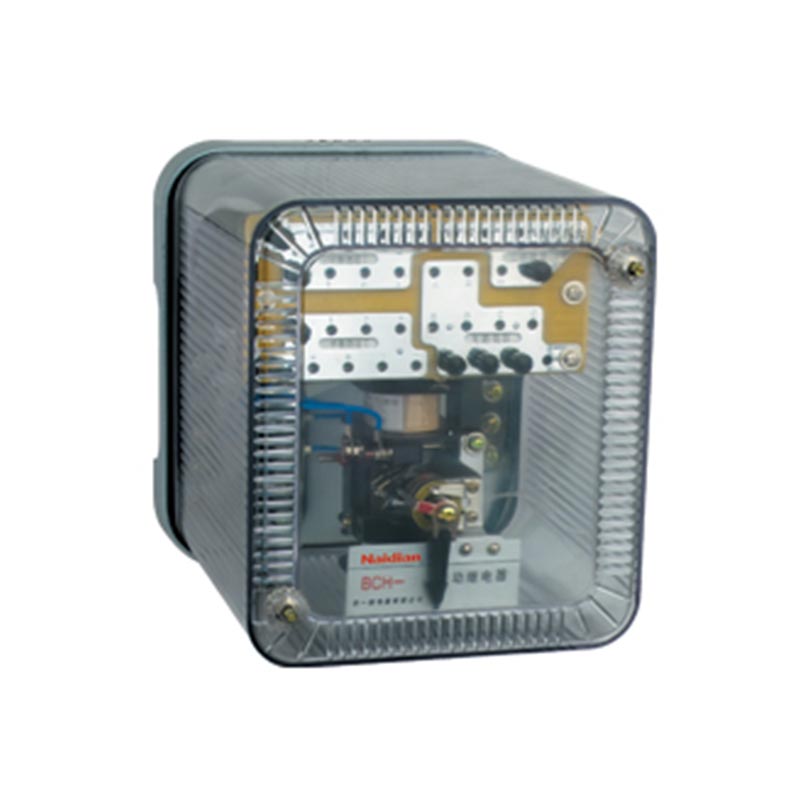
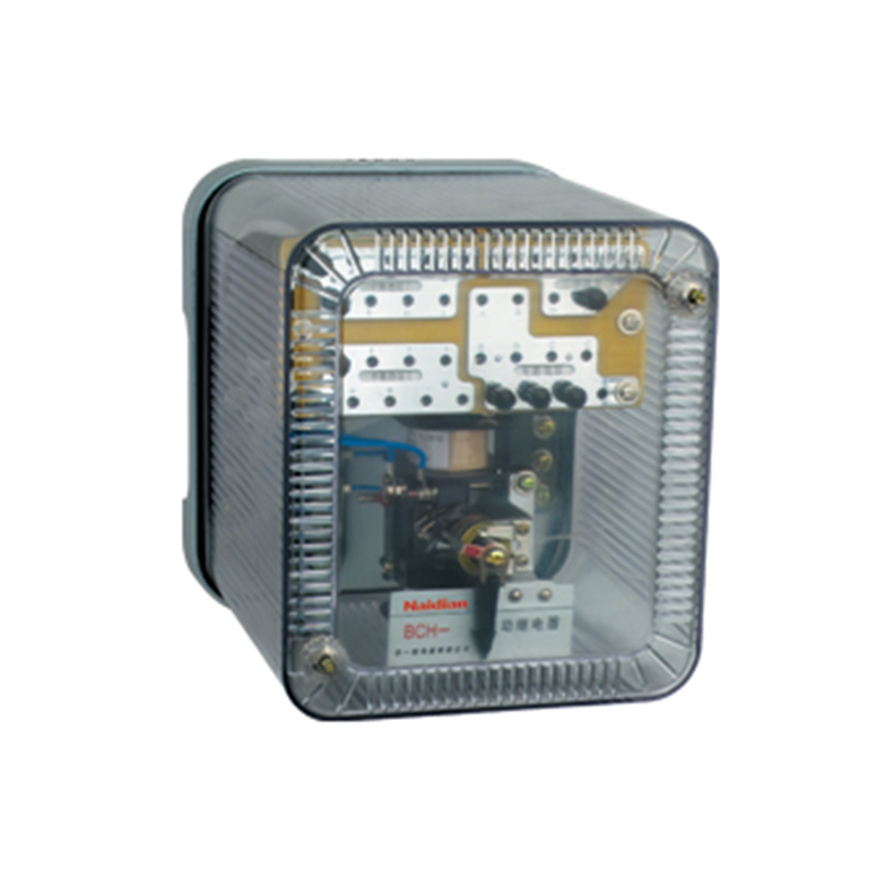
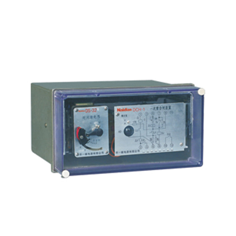
Structure
The device consists of a time relay (TYPE DS-32C as the time element), an intermediate relay (as the intermediate element), and a number of resistors and capacitive elements, which are fixed to an insulated mounting plate which is fixed to a metal base.The device has a metal case which is fastened to the base by a screw.The device has a clear plastic cover.The operation of the device can be observed from the outside.
See Fig.1 for the wiring diagram inside the device.
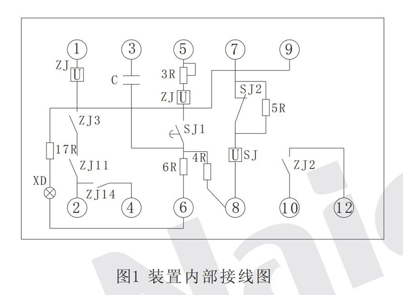
ZJ(I)- The current winding of the intermediate element
5R- Additional resistance to ensure thermal stability of time element coils
ZJ(V)- Voltage winding of intermediate element
6R- Discharges resistance when reclosing
SJ- Time element
17R- Reduces the voltage attached resistance on the signal lamp
C - capacitor
XD - light
4R- Charging capacitance
3R- Adjust charging time potentiometer
The device consists of the following components (technical data are shown in Table 1). Their main functions are as follows:
2.1 Time element SJ
The DS-32C time relay has a delay adjustment range of 0.25-5s.It is used to adjust the time delay between the device starting and the pulse rush to close the circuit breaker's closing coil.The time element has two pairs of delay moving contact and two pairs of instantaneous conversion contact.
2.2 Intermediate element ZJ
Type DZK-226 intermediate relay, which is the outlet element of the device for sending pulses to close the breaker closing coil circuit.The coil of the relay is composed of two windings. The voltage winding ZJ(V) is used for starting the intermediate element.The current winding ZJ(V) is used to keep the armature in the closing position after the intermediate element is started.
2.3 Capacitor C
Used to ensure that the device operates only once
2.4 Charging resistance 4R
Used to limit the charging speed of a capacitor
2.5 Additional resistor 5R
Used to ensure the coil thermal stability of time element SJ
2.6 Discharge resistance 6R
The capacitor is discharged through it during protective action, but reclosing should not be performed (reclosing is prohibited).
2.7 Signal lamp XD
In the wiring of the device, monitor whether the charging and discharging resistance capacitance and intermediate elements in the device and whether the voltage coil is normal.
2.8 Additional resistance is 17R
Used to limit the current flowing through the semaphore XD.
|
Generation of no. |
Name |
Voltage regulation, |
Note |
|||
|
220V- |
110V- |
|||||
|
ZJ( I) ZJ( V) |
Intermediate components |
Current specification( A) |
2 . 5 |
Same as 110V |
W1=30 turn x 2 Q-0.9 W2=5080turn x 2 Q- 0.14 |
W 1 is the number of turns of ZJ(I). W 1 is the number of turns of ZJ(V) |
|
1 |
Same as 110V |
W1=60turn x2 Q-0.62 W2=5080turn x2 Q- 0.14 |
||||
|
0.5 |
Same as 110 V |
W1=120turn x2 Q-0.44 W2=5080turn x2 Q-0.14 |
||||
|
0 . 25 |
Same as 110 V |
W1=240turn x2 Q-0.31 W2=5080turn x 2 Q-0.14 |
||||
|
SJ |
The time element |
12000 turn QQ- 0.15 |
5600 turn QQ- 0.23 |
Two parallel |
||
|
C |
capacitor |
CZJD- 1 - 250 - II 10 u F |
CZJD- 1 - 250 - II 20 u F |
Two parallel |
||
|
4 R |
Resistance |
RJ- 1 - I 3MΩ |
RJ- 1 - I 1.5 MΩ |
|
||
|
5 R |
Resistance |
RXY- 20 - I 2.7kΩ |
RXY- 20 - I 680Ω |
|
||
|
6 R |
Resistance |
RJ- 2 - I 510Ω |
RJ- 2 - I 510Ω |
|
||
|
17 R |
Resistance |
RJ- 2 - I 3 MΩ |
RJ- 2 - I 1.5MΩ |
|
||
|
XD |
Light |
NHO- 4 C |
NHO- 4 C |
Screw with socket |
||
|
3 R |
Potentiometer |
WX 3 - 11 2.7KΩ |
WX 3 - 11 2.7KΩ |
|
||
Action principle
3.1 Primary recloser device for single-end power supply (see Figure 2)
The position of the contact in the figure corresponds to the normal operation of the transmission line;The circuit breaker is in the closing position, the capacitor C in the reclosing device has been fully charged through the button contact EF and the resistor 4R, and the whole device is ready for action.The operating principle of the device is explained in the following aspects:
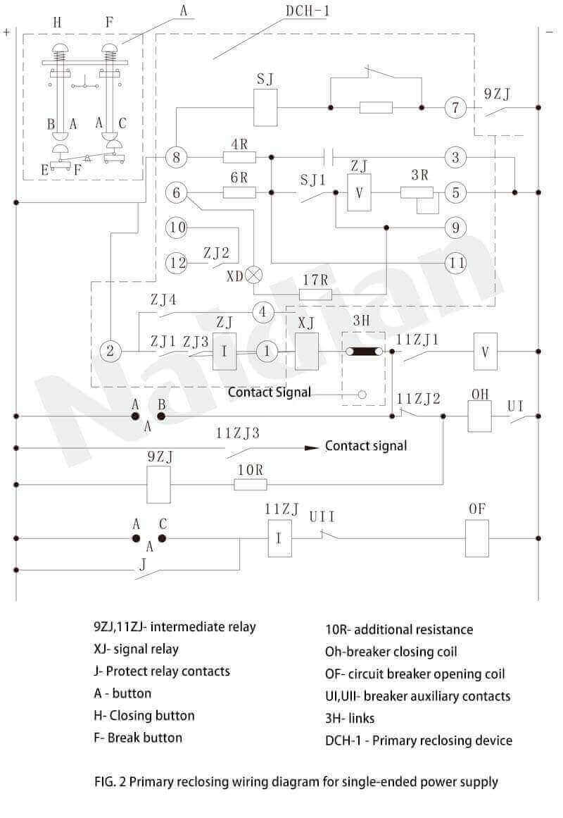
3.1.1 Circuit breaker tripping due to protective action or other reasons (contact J is closed)
At this point, the auxiliary contact UI of the circuit breaker returns, and the intermediate relay 9ZJ starts (10R is used to limit the current to prevent the circuit breaker closing coil OH from starting at the same time). After the contact is closed, the time element SJ of the reclosing device is started. After delay, contact SJ1 and contact closure after delay, capacitor C discharges ZJ(V) through SJ1.After ZJ(V) is started, the circuit breaker closing circuit (by +→EF→ →ZJ1→ZJ(I)→ →XJ→3H→11ZJ2→OH→UI→-)OH, to achieve a reclosing, at the same time, the signal relay XJ sends out a signal, because of the role of ZJ(I), so that contact ZJ1,ZJ2 can self-hold until the circuit breaker is completed closing, its contact UI is disconnected.If a temporary fault occurs on the line, after the successful closing, the capacitor is charged at its own will, and the device is in a state of reactivation.
3.1.2 If there is a permanent fault on the line
At this time, the reclosing fails the second trip of the circuit breaker, 9ZJ and SJ are still started together, but since this period of time is far less than the time (15-25s) necessary for capacitor charging to make ZJ(V) start, the device is guaranteed to operate only once.
3.1.3 The contact ZJ1 of the intermediate element of reclosing device is stuck or fused
In order to prevent in this case circuit breaker closing to the permanent fault lines for many times, in 11 what zj had intermittent electric appliance, because when circuit breaker closing on permanent fault, contact J closed again trip circuit (+ - J - 11 what zj had (I) - the UII - OF - -) 11 what zj had (I) started, if ZJ1 has welding or stuck, the intermediate relay through 11 what zj had (V) from keeping, and through 11 zj3 signal, a dynamic fault contact 11 zj2 disconnect the closing coil circuit, thereby preventing the circuit breaker closing for many times.
3.1.4 Manual trip
When F is pressed, the circuit breaker trips. Since EF has been disconnected, the starting circuit of the device is cut off to prevent the circuit breaker from closing.
3.1.5 Manual closing
(in the device should be taken before finished capacitor C discharge) when press the H, C charging circuit according to the current container (+ - EF - today - 4 r - C - 3 - -) at this time if there is a permanent faults in existence on the transmission line, the circuit breaker is removed again soon, because the capacitor to charge to make what ZJ had voltage (V) to start the necessary, so as to avoid the circuit breaker closing.
3.2 Primary reclosing device for double-end power supply (see FIG. 3 omitted)
The difference between FIG. 3 and FIG. 2 is only that the commutator line composed of contact YJ1 and YJ2 of the synchronous check relay contact TJ and connector 9H are added in the starting circuit of the reclosion device to perform the task of checking the line for no voltage or line synchronization.Neon lamp ND is used to indicate the realisation of the recalcitrance of transmission lines supplied by two ends.On one side of the transmission line, it is usually used to check the non-voltage connection of the line, while on the other side, it is used to check the synchronous connection of the line, and the reclose operation of the non-voltage side of the line should be ensured (see Figure 4), which will be described below respectively.
3.2.1 9H in the position of no power in the line (see FIG. 3 and 4 omitted)
YJ is the low voltage relay, and the positions of contacts YJ1 and YJ2 correspond to the situation when there is no voltage in the relay coil.
Therefore, YJ2 is allowed to start the reclossing device only after the trip of the opposite circuit breaker is confirmed (i.e., there is no circuit voltage). In addition, it is not allowed to start the device when there is a large electrostatic voltage caused by residual charge on the circuit.
3.2.2 9H is in the position of line synchronization check (see Figure 3 omitted)
At this point, as the opposite end has been closed, the voltage appears on the line, and YJ1 should be closed.If size of busbar voltage, phase and the size of the line voltage, within the scope of the allow the closing of the difference in phase (i.e. think synchronization), then sync check relay contact TJ in the closed position (as shown in figure 3 a), reclosing device can start right now, and if the relevant large TJ start appear (asynchronous), the open contact, reclosing device cannot start.
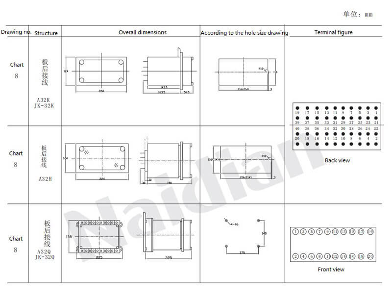
External structure and installation hole size
The relay adopts A32K,A32H and A32Q housing, and the outline structure and installation opening diagram are shown in figure 8 attached to this manual.
Message feedback
News Center
Naidian Group is an electronic timer manufacturer and digital timer supplier, providing high-power relays, electronic time relays, digital timer relays, DC to AC solid state relays, and digital display timer relay knowledge popularization.
On February 26, the production of NPOWER Group resumed. The director and manager of our company personall...
Regular relays: ≤10A control/small loads. Power relays: >10A & high voltage, with arc suppression/thermal...
Digital time relay is an electronic device that uses digital circuit technology to achieve time delay con...
A specialized relay designed to detect and respond to alternating (AC) or direct (DC) current deviations ...

GET A QUOTE