Phone number:0086-0577-61731588
Fax:0086-0577-61731588
Cell phone:+86 18072180777
Wechat:+86 18072180777
Website:www.china-relay.com
Zhiguang Industrial Zone, Liu Town, Yueqing, Zhejiang, China
Rated voltage: 110,220
Intermediate element: 0.25
Rated current: 0.5,1,2.5,4
Reclosing interval: 15~20
Delay setting range: 0.25~3.5
Power consumption: ≤1.35
Dimensions: Length * width * height 175*195*210
Usage
It is used in the control loop of three-phase primary reclosing on the transmission line.
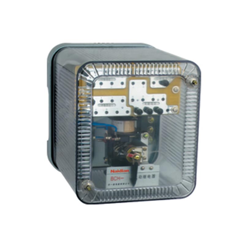
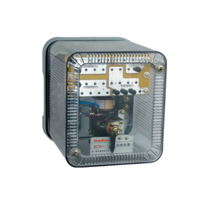
Summary of structure
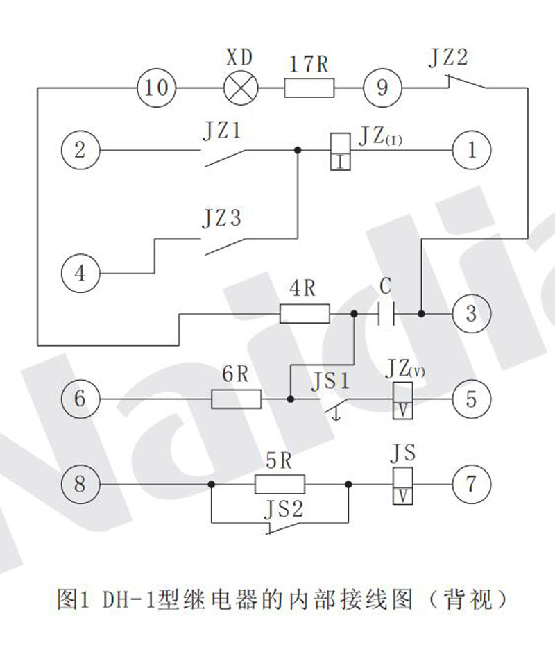
The relay consists of a time relay (DS-112C, as the time element JS), a code relay (as the intermediate element Jz), and a resistance and capacitance element.They are fixed on the insulating mounting plate, which is fixed on the metal base and equipped with the metal shell. It is fastened on the base by screw, and there is a dust separator between the shell and the base to ensure the seal. There is glass on the upper part of the metal shell to check the operation of the device from the outside.
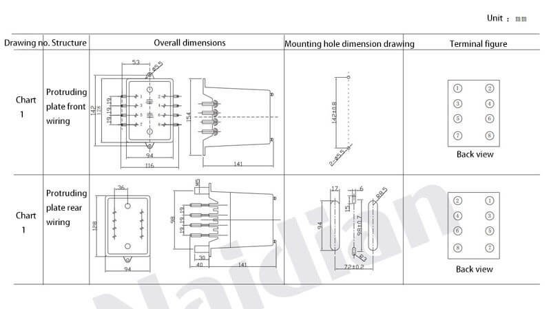
The relay may be connected in front of the board or behind the board.
The internal wiring diagram of the relay is shown in Figure 1
Ordering instructions
Please make clear when placing an order
1. Name and model of the relay.
2. Rated voltage of operating circuit, rated current of intermediate element current winding JZ (I).
3. Connection mode (front or back)
When selecting the specification of the device, the rated current of the intermediate element current winding JZ (I) shall be less than the rated current of the breaker closing contactor coil.The details can be selected according to Table 2.
Table 2
|
Rated current of circuit breaker closing contactor coil( A) |
0.3 - 0.6 |
0.6-1.2 |
1.25-3 |
3-7.5 |
|
Rated current of the relay( A) |
0.25 |
0.5 |
1 |
2.5 |
Technical data
1. Rated voltage of the relay is DC110V and 220V.
2. Rated current of the relay (rated holding current of the intermediate element current winding JZ(I)) is 0.25a, 0.5a,1A,2A,4A.
3. At rated voltage, when the ambient temperature is 20+5℃ and the relative humidity is not more than 70%, the time between charging and the voltage necessary for the action of the intermediate element (the time between a recalculation) is within the range of 15S-25s.
4. At the rated voltage of 70%, when the ambient humidity is 20+5℃ and the relative humidity is no more than 70%, the relay shall ensure reliable operation. At this time, the time for capacitor charging to the voltage necessary for the intermediate element to operate is allowed to be extended to 2min.
5. When the voltage winding of the intermediate element has no voltage and the current winding flows through the rated current, the armature is kept in the suction position.
6. After connecting the contacts JZ1 and JZ(I) of the intermediate elements at rated voltage in series, the relay shall ensure that the current of 8 times (not more than 8A) of the rated current can be switched on for 5s, after which there shall be no trace of melting and bonding on the contacts.
7. At rated voltage, the power consumption of the intermediate element current winding JZ(I) shall not be greater than 1.35W.
8. The delay adjustment range of time elements is 0.25s-3.5s.
9. The time element should be able to withstand 110% rated voltage for a long time after the coil is attached in series.
10. Dielectric strength: each circuit of the relay shall be able to withstand voltage 2kV, AC 50Hz test lasting for 1min between exposed non-charged metal parts without breakdown or flashover.
The parameters of each component in the relay are given in Table 1
Table 1
|
Wiring diagram code |
Name |
Rated Voltage |
Note |
|||
|
110V |
220V |
|||||
|
ZJ( I) ZJ( V) |
Intermediate components |
Rated Current ( A) |
0 . 25 |
W 1 = 1200turnW 2 = 8000turn Φ= 0 . 35 R= 12 . 3Ω Φ= 0 . 12 R= 900Ω |
W 1 = 1200turn W 2 = 12600turn Φ= 0 . 35 R= 12 . 3Ω Φ= 0 . 1 R= 2100Ω |
W 1 is the number of turns of JZ(I) W 2 is the number of turns of JZ(V)
|
|
0 . 5 |
W 1 = 600turn W 2 = 8000turn Φ= 0 . 49 R= 3 . 2Ω Φ= 0 . 12 R= 900Ω |
W 1 = 600turn W 2 = 12600turn Φ= 0 . 49 R= 3 . 2Ω Φ= 0 . 1 R= 2100Ω |
||||
|
1 |
W 1 = 300turn W 2 = 8000turn Φ= 0 . 69 R= 0 . 8Ω Φ= 0 . 12 R= 900Ω |
W 1 = 300turn W 2 = 12600turn Φ= 0 . 69 R= 0 . 8Ω Φ= 0 . 1 R= 2100Ω |
||||
|
2 . 5 |
W 1 = 120turn W 2 = 8000turn Φ= 1 R= 0 . 2Ω Φ= 0 . 12 R= 900Ω |
W 1 = 120turn W 2 = 12600turn Φ= 1 R= 0 . 2Ω Φ= 0 . 1 R= 2100Ω |
||||
|
4 |
W 1 = 75turn W 2 = 8000turn Φ= 1 . 32 R= 0 . 05Ω Φ= 0 . 12 R= 900Ω |
W 1 = 75turn W 2 = 12600turn Φ= 1 . 32 R= 0 . 05Ω Φ= 0 . 1 R= 2100Ω |
||||
|
JS C 4 R 5 R 6 R 17 R |
Time element capacitor resistance Resistance resistance resistance |
W 1 = 9800turn Φ= 0 . 2,R= 450Ω CZM- L- 250 - 10 uf RT- 0 . 5 - 2 . 2 MΩ RXY- 20 - 1 KΩ RXY- 15 - 500Ω RXY- 20 - 1 KΩ |
W 1 = 17600turn Φ= 0 . 13,R= 1930Ω CZM- L- 630 - 4 uf RT- 0 . 5 - 6 . 8 MΩ RXY- 20 - 4 KΩ RXY- 15 - 500Ω RXY- 20 - 3 KΩ |
Two in parallel two in parallel |
||
Appearance and hole size
See Figure 1 attached to this manual for outline dimensions and opening dimensions.
Message feedback
News Center
Naidian Group is an electronic timer manufacturer and digital timer supplier, providing high-power relays, electronic time relays, digital timer relays, DC to AC solid state relays, and digital display timer relay knowledge popularization.
On February 26, the production of NPOWER Group resumed. The director and manager of our company personall...
Time: December 5th - December 7th, 2024. Booth No.: 5P66, Hall N5 Add: Halls N1 - N5 and W5, Shanghai New...
There are five main advantages of choosing a time relay, namely, Control voltage, Functional requirements...
Time relays are usually used in circuits with lower voltage or lower current to control circuits with hig...

GET A QUOTE