Phone number:0086-0577-61731588
Fax:0086-0577-61731588
Cell phone:+86 18072180777
Wechat:+86 18072180777
Website:www.china-relay.com
Zhiguang Industrial Zone, Liu Town, Yueqing, Zhejiang, China

Setting voltage:
Overpressure: 60V 200V 400V
Low pressure: 48V 160V 320V
Setting error :≤±3%
Return coefficient :≥0.85
Return time :1.2 times ≥0.15s3 times ≥0.03s
Contact capacity :DC50WAC250VA
Contact form: move and close, move and close and break,
Two move break move close, two move close move break
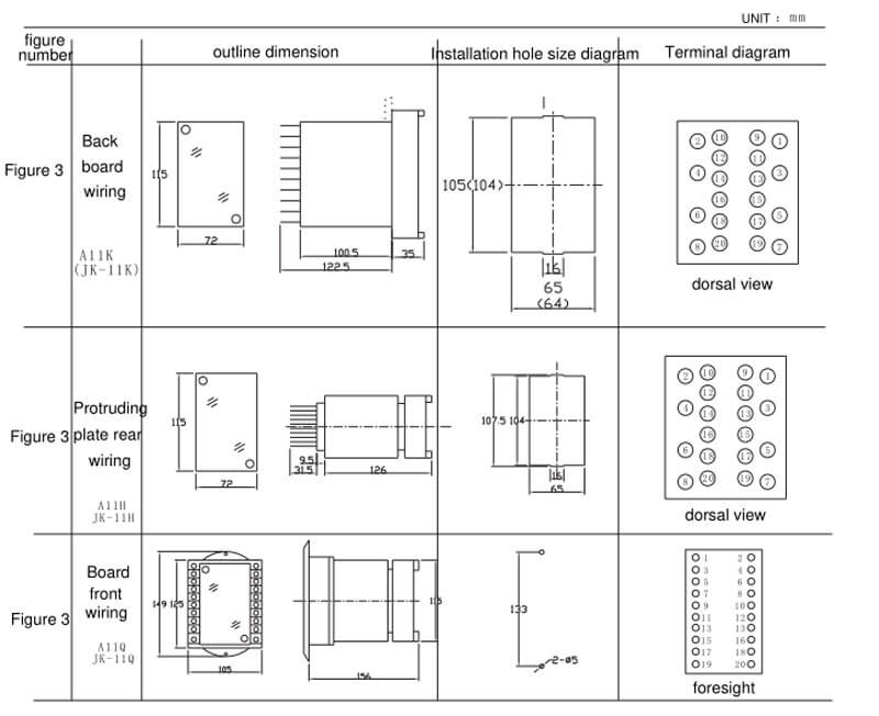
Opening size :107.5×62.5mm
Installation method: Adopt A11K, A11H, A11Q shell
Usage
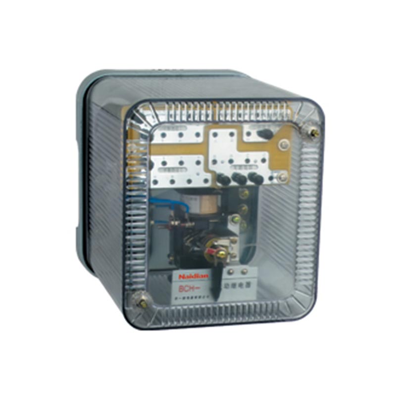
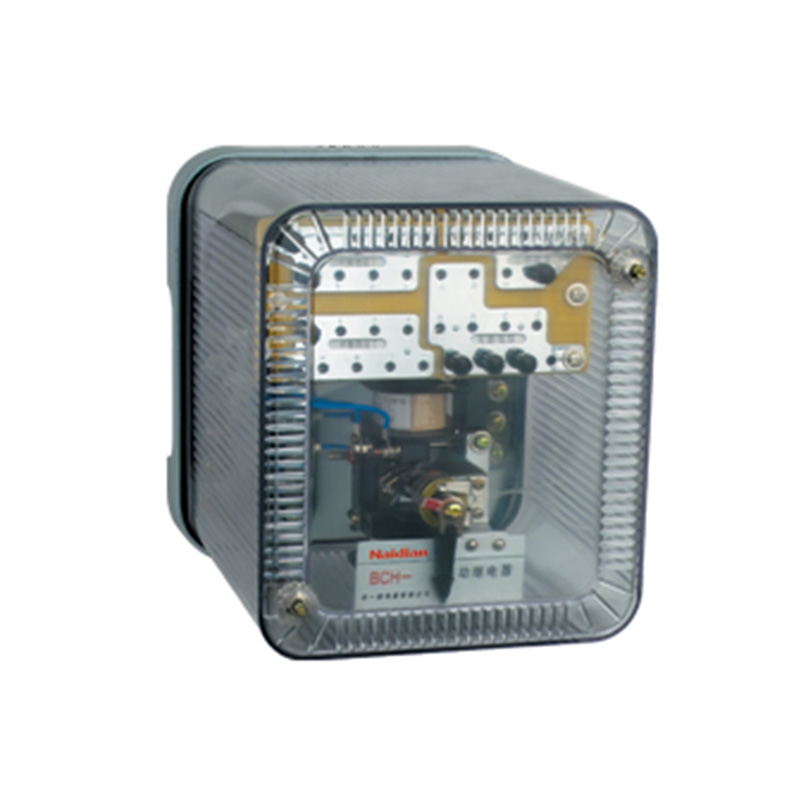
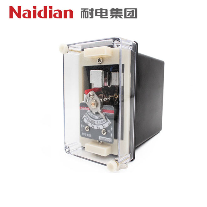
DY-30 series voltage relays, used in relay protection lines as operating elements for overvoltage protection or low voltage latching.
Structure and principle
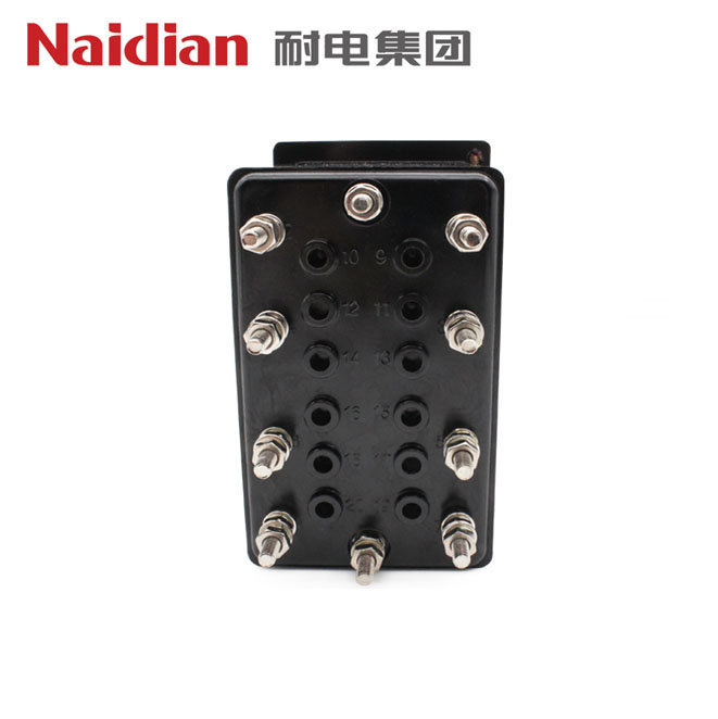
1. The relay is electromagnetic and operates instantaneously. The magnetic system has two coils, the head of which is connected to the base terminal.
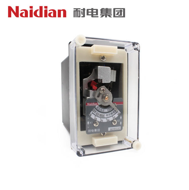
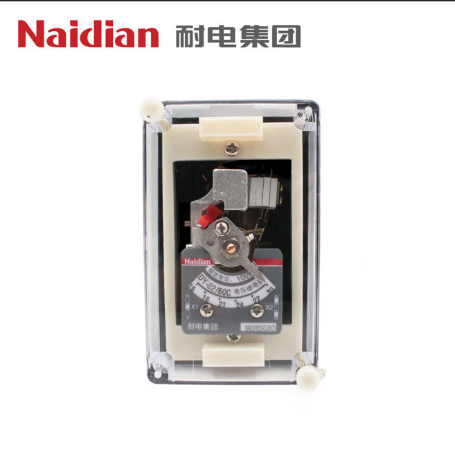
2. The calibration value and rating of the relay name brand are in units of V when the coils are in parallel.The action value of the relay can be changed by turning the pointer on the dial to change the reaction moment of the hairspring.
3. Relay action: For over-voltage relay, when the voltage rises to or exceeds the setting value, the relay will act, and the moving closing contact will close, while the moving breaking contact will break.When the voltage drops to 0.8x setting value, the relay returns, the moving closing contact disconnects and the moving breaking contact closes. For the low-voltage relay, when the voltage drops to the setting voltage, the relay operates, the moving closing contact disconnects and the moving breaking contact closes.
4. See Figure 1 for the internal wiring diagram of the relay.
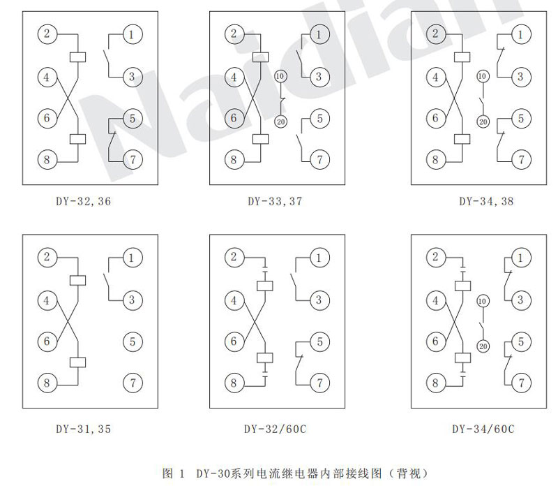
Figure 1 Internal wiring diagram of DY-30 series current relay (back view)
Use and maintenance
1. Before the use of the relay, the casing shall be removed and the machine shall be pulled out to check whether there is any damage caused in transportation;If the moving plate touches the magnetic plate, the coils of the spring thread collide, and the friction on the shaft of the moving plate, for this reason, set the pointer of the relay at the first point, rotate the movable system in the direction of the magnetic plate by hand, and then let go. The movable system should be turned back to the original balance position until the stop, and then make necessary adjustment and setting.
2. When the relay is readjusted, it must be guaranteed.
2.1 The axial activity of the movable system is between 0.15-0.3mm.
2.2 The air gap between the moving plate and the magnetic pole shall ensure that the moving plate and the magnetic plate shall not collide under any specified working conditions of the relay.
2.3 For relays with moving and breaking contacts, bridge contacts shall not touch moving and breaking contacts at the same time in the process of operation.
2.4 When the pointer rotates from the first scale value to the final scale value, the rings of the hairspring shall not touch.
2.5 When the relay operates, the popular contact should slide (tolerance +1mm) on the center line of the static contact and move.The total air gap of static contact is not less than 2mm.
2.6 The distance between the stationary contact and the limiting piece shall not be greater than 0.3mm.
2.7 When adjusting the operation value of the relay, the adjustment of the minimum setting value is mainly to change the reaction force of the hairspring, while the adjustment of the maximum setting value is mainly to change the air gap between the moving plate and the magnetic plate.
2.8 The relay shaft and bearing shall not be lubricated.
2.9 It is not allowed to use sandpaper or other rough materials to clean the contacts. It is advisable to use a sharp blade or clean the contacts, and then wipe them with a clean and soft cloth to avoid touching the contacts with fingers.
Technical data
1. The number of contacts is shown in Table 1
Table 1
|
Model |
The quantity of Contact |
|
|
Normal Open |
Normal Close |
|
|
DY-31 , 35 |
1 |
|
|
DY-32 , 36 |
1 |
1 |
|
DY-33 , 37 |
2 |
1 |
|
DY-34 , 38 |
1 |
2 |
|
DY-32 / 60 C |
1 |
1 |
|
DY-34 / 60 C |
1 |
2 |
2.According to the range of setting value, the operating error of each setting value is no more than +6%. Various technical data of the relay are shown in Table 2.
Table 2
|
Model |
Maximum setting voltage(V) |
Rated voltage(V) |
Long term allowable voltage(V) |
Voltage setting range(V) |
Action voltage(V) |
|||
|
Coil in parallel |
Coil in series |
Coil in parallel |
Coil in series |
Coil in parallel |
Coil in series |
|||
|
DY-32/60C DY-34/60C |
|
100 |
200 |
110 |
220 |
15 - 60 |
15 - 60 |
30 - 60 |
|
DY-31 DY-32 DY-33 DY-34 |
60 |
30 |
60 |
35 |
70 |
15 - 60 |
15 - 60 |
30 - 60 |
|
200 |
100 |
200 |
110 |
220 |
50 - 200 |
50 - 100 |
100 - 200 |
|
|
400 |
200 |
400 |
220 |
440 |
100 - 400 |
100 - 200 |
200 - 400 |
|
|
DY-35 DY-36 DY-37 DY-38 |
48 |
30 |
60 |
35 |
70 |
12 - 48 |
12 - 24 |
24 - 48 |
|
160 |
100 |
200 |
110 |
220 |
40 - 168 |
40 - 80 |
80 - 160 |
|
|
320 |
200 |
400 |
220 |
440 |
80 - 320 |
80 - 160 |
160 - 320 |
|
Note: DY-32/60C,DY-34/60C are long-term thermal stable (with built-in series capacitance) voltage relays.
3. Relay calibration limit error: not more than 6%.
4. Variation of action value: no more than 6%.
5. The return coefficient of dY-31,32, 34 voltage relay is not less than 0.8;Dy-35,36,37,38 Low voltage relay return coefficient not greater than 1.25.
6. Action time
6.1 For overvoltage relay
When the action value is 1.1 times, the action time is no more than 0.12s.At 2 times of the action value, the action time is no more than 0.04s.
6.2 For low voltage relays
When the working voltage of the relay is 0.5 times the setting voltage, the operation time shall not be greater than 0.51s.
7. Overvoltage capability: When the coils are connected in parallel, the voltage is uniformly raised from zero to 1.05-2.2 times of the setting voltage at the minimum setting value. Within this range, the relay should not vibrate to make the moving contact stop working.After this test, the relay shall still be able to meet the requirements of the technical conditions.
8. Overvoltage: when the setting value of the relay is added 1.75 times or higher, the moving contact of the relay shall close without jitter.
9. When there are no external collisions and vibrations.When the working voltage at each setting position (except the first point) of the over-voltage relay is 0.6 times the setting value, its dynamic breaking contact should close the circuit reliably.
10. When the operating voltage of the low-voltage relay is 0.6 times the setting voltage or lower, its dynamic breaking contact shall be closed without jitter.
11. When there is no external collision or vibration, when the working voltage at each setting position of the low-voltage relay is not less than 1.5 times the setting voltage, its moving contact should be able to close the circuit by ground.
12. At operating and return voltages: the moving system of the relay should not be stuck in the middle.
13. When the relative humidity is not more than 85% of the surrounding air, the relay circuit to shell (shell of conductive metal part) of the insulation resistance, using the 500 v megohmmeter, measure shall be not less than 300 m Ω.
14. The insulation of the conductive part of the relay to the housing (non-conductive metal part of the housing) can withstand a test lasting 1min at 50Hz ac voltage of 2kV.
15. Contact disconnection capacity: When the voltage is no more than 250V and the current is no more than 2A, the disconnection power of the contact is 50W in the DC circuit with inductive load (time constant is no more than 5x10s) and 250VA in the AC circuit.
16. Power consumption: At the minimum setting value, the power consumed by the relay coils shall not exceed 20VA.
17. When the temperature of the surrounding medium is +40℃, when the relay operates under the long-term allowable current and voltage as shown in Table 2 and Table 3, there will be no damage to insulation and other electrical components, and the temperature rise of the coil will not be greater than 65℃.
18. Life: the electrical life of the relay is 500 times, and the mechanical life is 5000 times.
Appearance and hole size
The relay adopts A11K,A11Q series housing, the outline and installation hole size are shown in figure 3 attached to this manual.
Message feedback
News Center
Naidian Group is an electronic timer manufacturer and digital timer supplier, providing high-power relays, electronic time relays, digital timer relays, DC to AC solid state relays, and digital display timer relay knowledge popularization.
On February 26, the production of NPOWER Group resumed. The director and manager of our company personall...
Time: December 5th - December 7th, 2024. Booth No.: 5P66, Hall N5 Add: Halls N1 - N5 and W5, Shanghai New...
There are five main advantages of choosing a time relay, namely, Control voltage, Functional requirements...
Time relays are usually used in circuits with lower voltage or lower current to control circuits with hig...

GET A QUOTE